This exercise is intended to help students to understand how to calculate a 3D point cloud from stereo images.
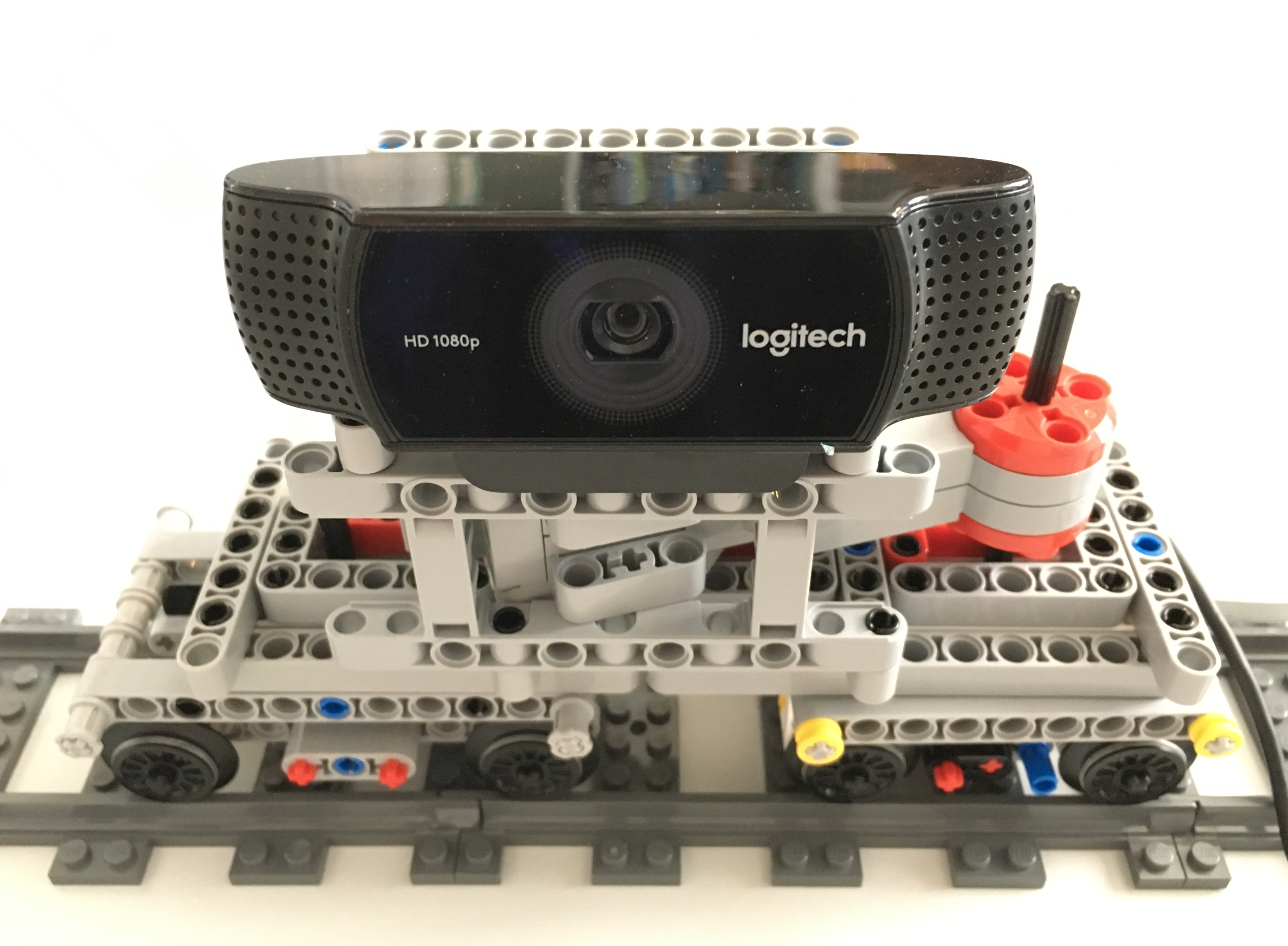
- Build a four-wheeled LEGO vehicle on rails with a single large motor with a RGB camera mounted on the vehicle facing to the side.
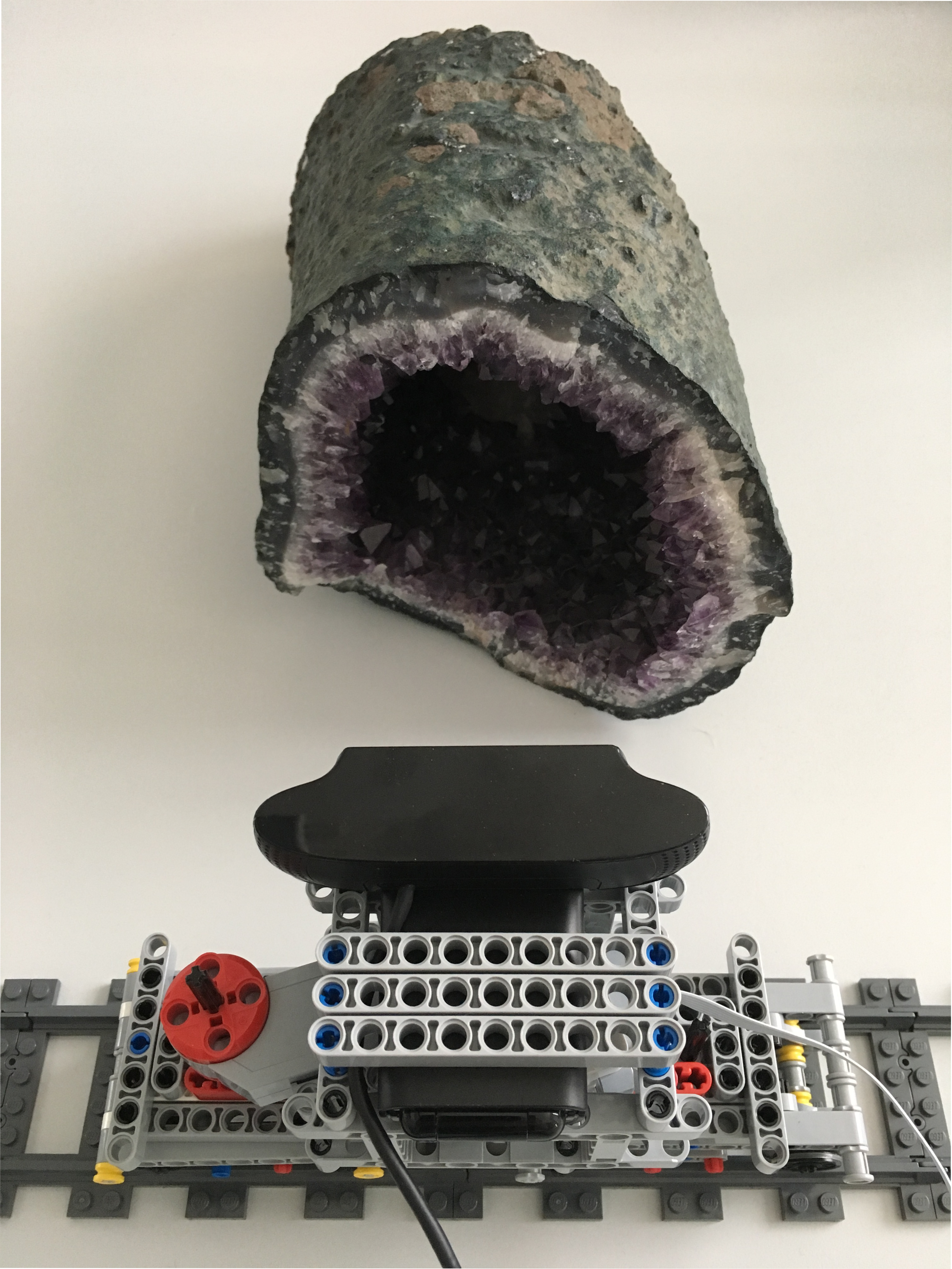
- Acquire 2D stereo images of a three-dimensional object of your choice with the RGB camera moved by the vehicle along an object of interest.
- Process and analyze the stereo images to calculate the 3D geometry of the object.
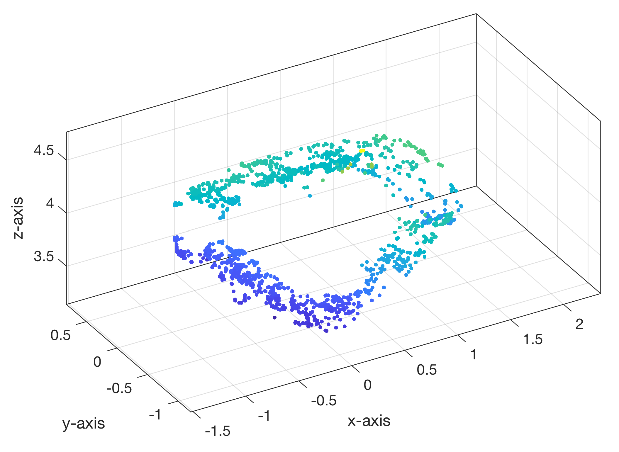
- Visualize a 3D point cloud from the stereo images.
Solution
- First you have to build the vehicle according to the LEGO building instructions. The building instructions are in a LXF file which can be opened with the free LEGO Digital Designer software, which is available for Computers running macOS or Windows. After launching the software you can use the view menu to switch from the construction mode to the building instructions mode.
- You need the Computer Vision Toolbox and a high-resolution RGB camera, which is supported by MATLAB, such as the Logitech C922 Pro Stream Webcam. To access the camera using MATLAB you need the appropriate hardware support package for your camera. Install the hardware support on your computer and read the documentation.
- In order to create the point cloud of the object, you first have to calibrate the camera. For this, you need a printout of the checkerboard pattern of which you have to take 3 to 20 pictures from different angles with the camera you want to calibrate. The checkerboard pattern can be obtained by typing “open checkerboardPattern.pdf” in the Command Window of MATLAB. The distance between the camera and the checkerboard should be about the same as to the object you want to record later. The calibration can be done with the Single Camera Calibration App. After you calibrated your camera following the instructions, you have to create a camera calibration file, which contains the intrinsic, extrinsic, lens distortion, and estimation properties for your camera.
- To generate the point cloud, you have to take two pictures from different positions with an overlap of approximately 60% or more. For the best results, you should use an object with clear structures and high contrasts. For this you need to take a picture, move the vehicle for short amount of time and take another picture. Your MATLAB script creates connections to the motor and the camera, moves the vehicle and acquire the images.
- Load the image files into MATLAB and apply the camera calibration file to remove image distortions.
- In order to determine the difference between the two images you have to define pairs of points clearly visible in both images. One method to fine these reference points is the detectMinEigenFeatures algorithm. To determine the transformation vector of each individual reference point between the two images you can use a point tracker.
- In order to located each individual reference point in the 3D space you have to find corresponding points in the two stereo images. This can be done with the essential matrix. Furthermore, you need to calculate the camera position and the camera projection matrix to project the images.
- With the function triangulate and the calculated and matched points you can calculate the location of all points in the 3D space and hence the 3D point cloud of the object.
- The point cloud can be visualized with pcshow.
LEGO building instructions and MATLAB script to run the experiment
Download the building instructions and MATLAB script. The LXF file contains the building instructions to be used with the free LEGO Digital Designer software available for macOS and Windows.